The ASUS ROG Maximus X Apex Review: X Marks the Spot, Literally
by Joe Shields on May 11, 2018 9:00 AM EST- Posted in
- Motherboards
- Intel
- Asus
- ROG
- Aquantia
- 5G
- Coffee Lake
- Z370
ASUS ROG Maximus X Apex Visual Inspection
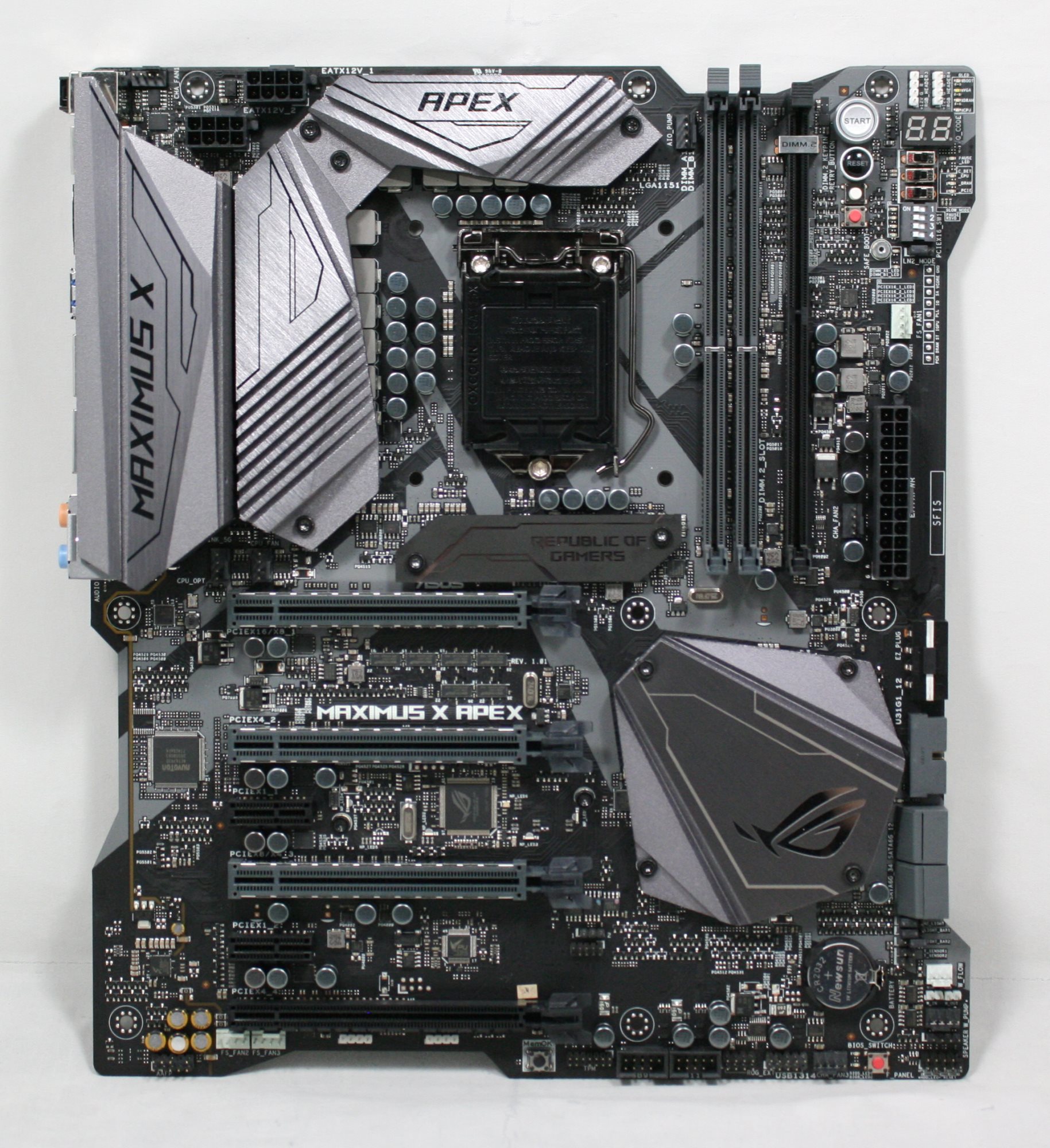
The ASUS ROG Maximus X Apex is a unique looking board, at least the shape. The E-ATX sized motherboard is actually meant to be "X" shaped, with some meat cut out of each side of the board giving it a kind of "X" shape, I guess? From a user practicality standpoint, the cutouts on the right side will help with cable routing as many cases and benching tables have the holes and grommets setup for ATX size. Outside of that, there is not an obvious reason for the cutouts apart from looking that little bit different.
The PCB is black and does have some grey stenciled design in the shape of an X running through the socket area. RGB LEDs are located on the bottom of the board, below the power delivery heatsink, in the ROG 3D printable area below the socket, and the below the chipset heatsink. Most of the motherboard is exposed rather than being covered up by a shroud, but that really isn't expected with this type of board. Personally, I prefer the exposed look rather than a full board covering, but that is my personal preference.
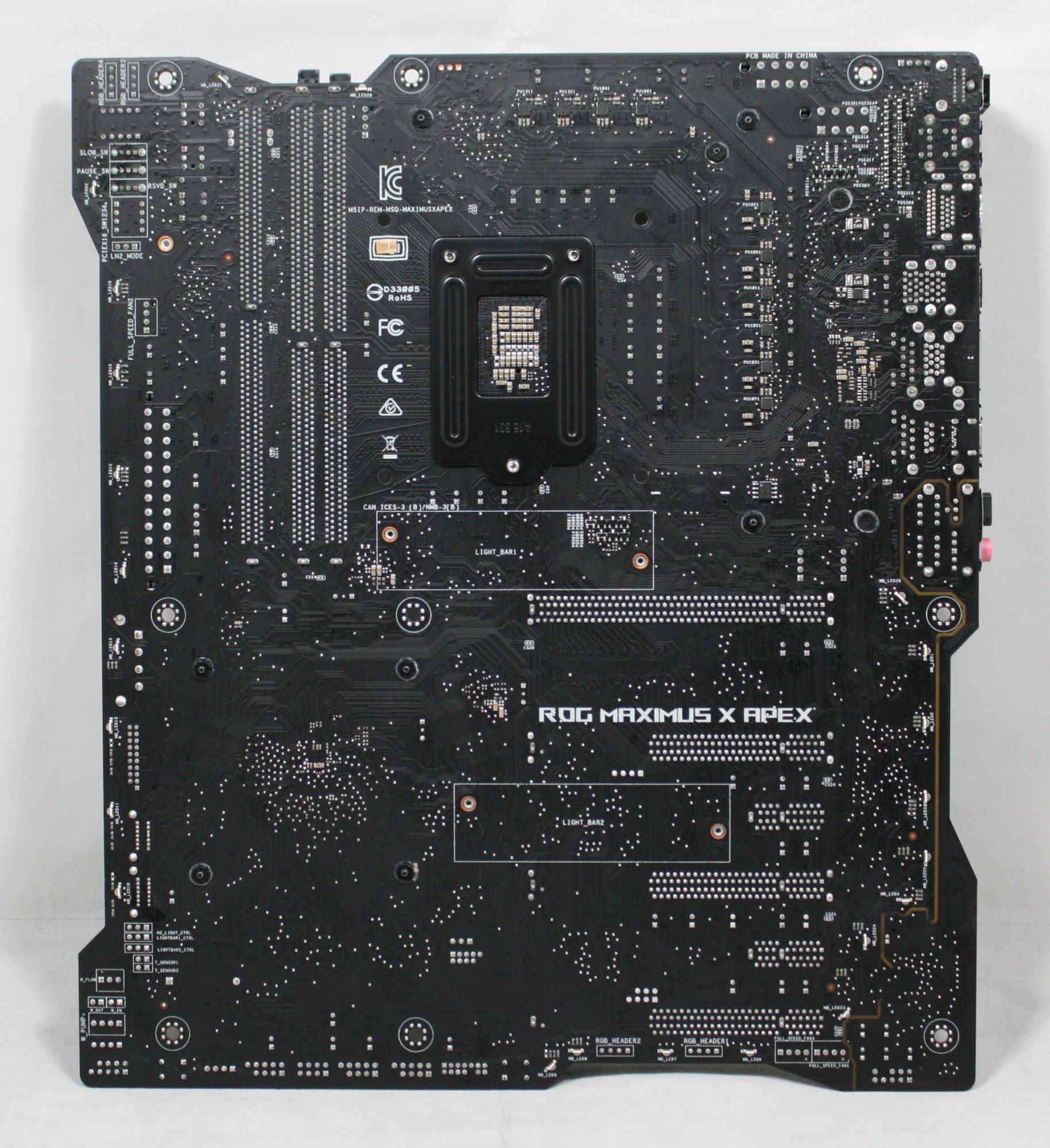
The PCB cutouts are more visible on the back of the motherboard. That being said, when was the last time a user showed off the back of a motherboard?
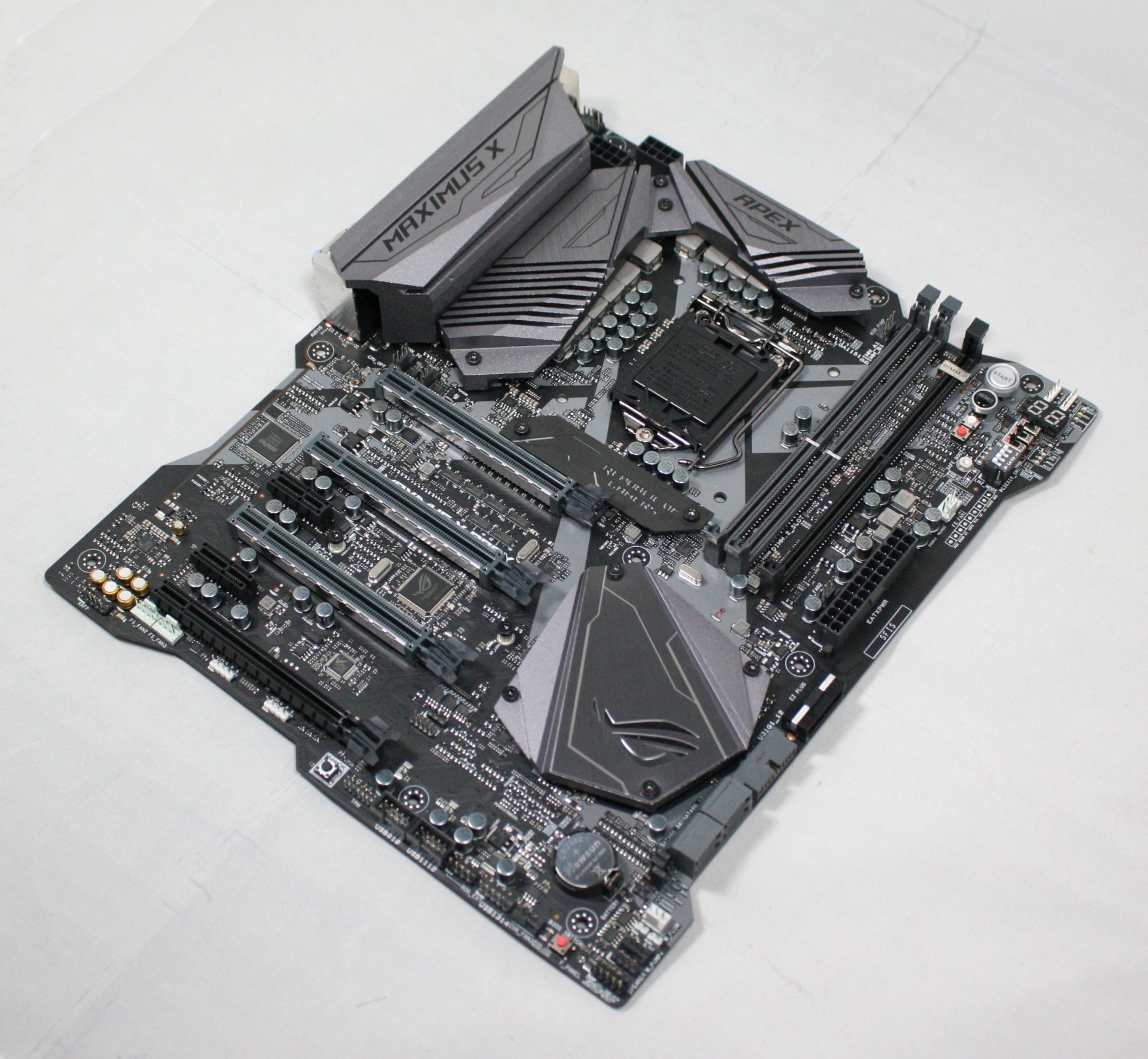
We are able to see a large grey brushed aluminum heatsink covering the power delivery area to keep it cool. The back IO area also has a beefy shroud made out of aluminum though it is mostly aesthetic as it is not making direct contact with the power delivery heatsink, but it does cool the Aquantia 5G chip. The chipset heatsink takes up a fair amount of space and keeps it cool.
Outside of the heatsinks, the board is generally designed to push limits and overclock, so ASUS chose to go with two slots for DRAM instead of the typical four we see on most full-size Z370 boards. This was done in order to optimize the memory trace length which ASUS says improves stability and performance. Also unique to the Apex is the ROG DIMM.2, a vertically-installed dual M.2 expansion card that includes a fan bracket to assist in keeping the M.2 drives cooler below it.
The Apex also has a whopping 10 fan/pump headers on the board along with water flow and in/out water temperature headers which makes the board a pretty comprehensive control center for ambient cooling on either air or water.
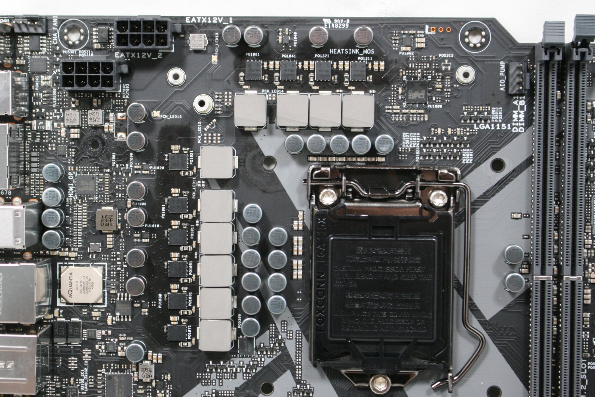
The power delivery area in the Apex is in an 8+2 mode using ASUS's 10K capacitors as well as microfine alloy chokes. Driving these are the ASUS ASP14501 which is set up in a 4+2 phase configuration. Each phase for VCore from the digital PWM has doublers via IR3599 phase doublers. Each doubler outputs to an IR3535 driver which we counted 10 on the backside (2 for iGPU, 8 for CPU). The MOSFETs are Infineon OptimMOS BSG0812ND rated at 50A. The VRMs are fed from two 8-pin EPS 12V connectors (one is optional) found in the upper left-hand corner.
The memory and CPU secondary rails use a two-phase controller for the memory and two N-channel MOSFETs. VCCSA and VCCIO source their power from a Texas Instruments TPS51362 converter and single phase VRM managed by Anpec PWM and PowerPAK MOSFETs.
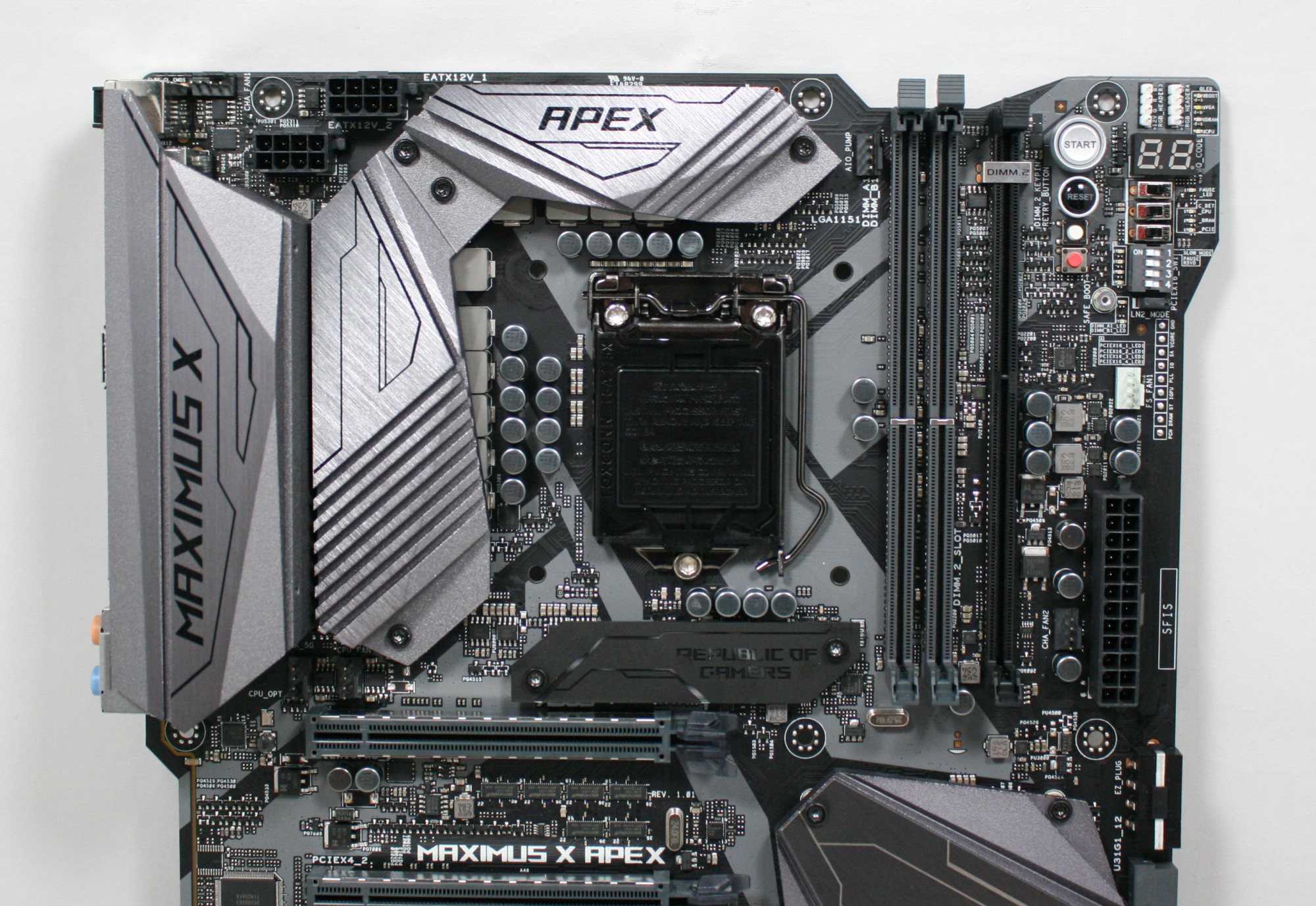
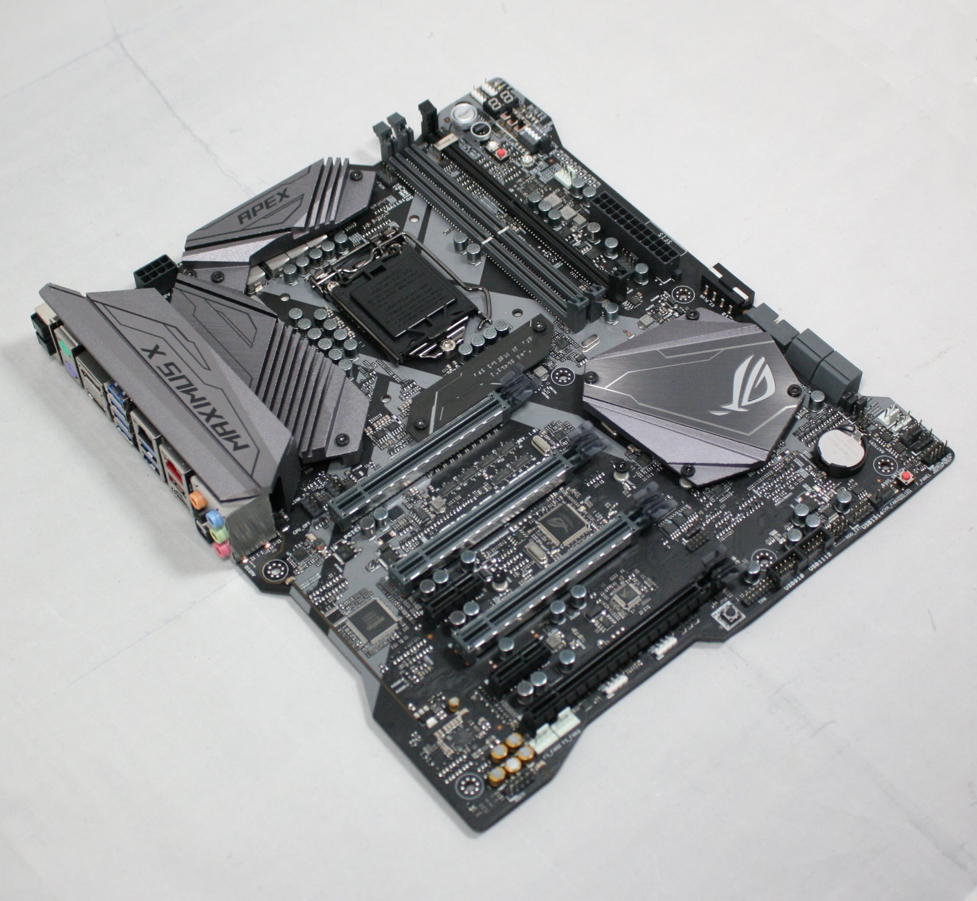
The top half of the board gives us a closer look at the heavy shrouds around the power delivery area and back panel IO. The socket area is fairly busy which can make insulation for sub-ambient overclocking a bit more tedious, trying to jam eraser between the caps and chokes. To the right side we see the two DRAM slots, the DIMM.2 slot as well as all the goodies ASUS added in that upper right-hand corner. Below the CPU socket and above the first PCIe slot is an aesthetic plate which can be customized with a 3D printer. ASUS includes a couple of blanks with the board.
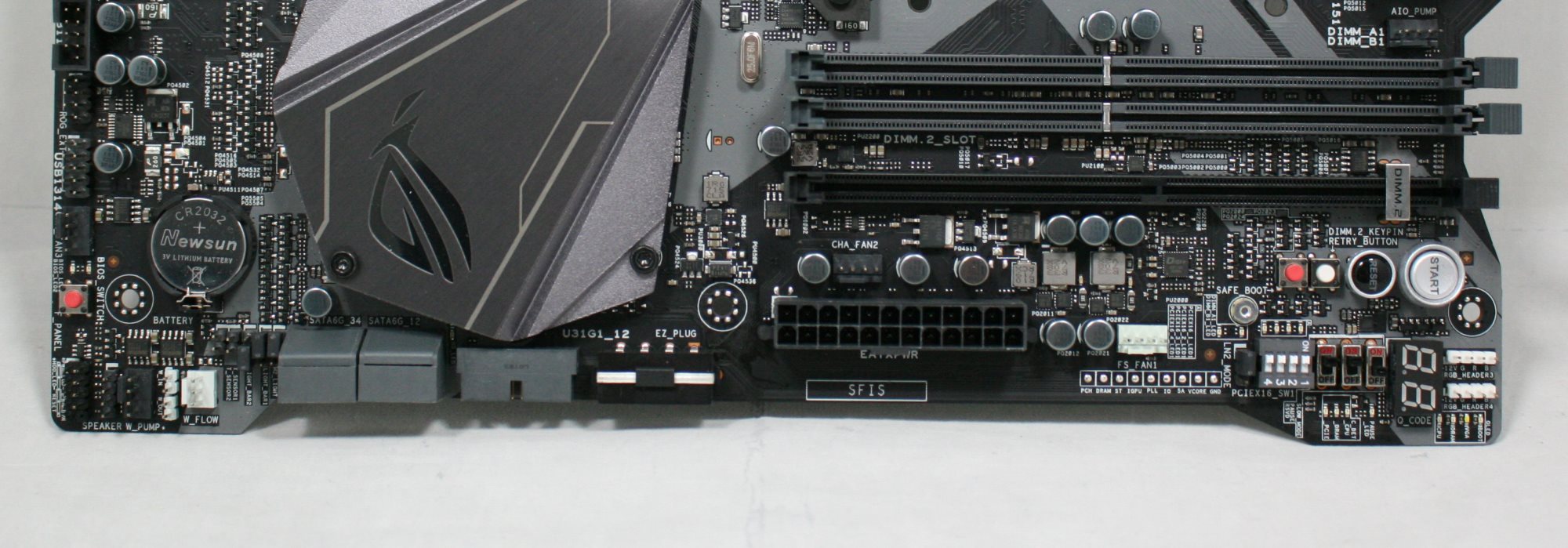
The right side of the board has quite a bit going on. There are fan, temperature and water flow headers, the four SATA ports as well as front panel USB 3.0 header and a Molex connector for additional power to the PCIe slots when running multiple GPUs. Continuing on to the right, we will run into the 24-pin ATX power lead and the FS Fan header. One thing I would liked to have seen on a board of this caliber is a front panel USB 3.1 header as well.
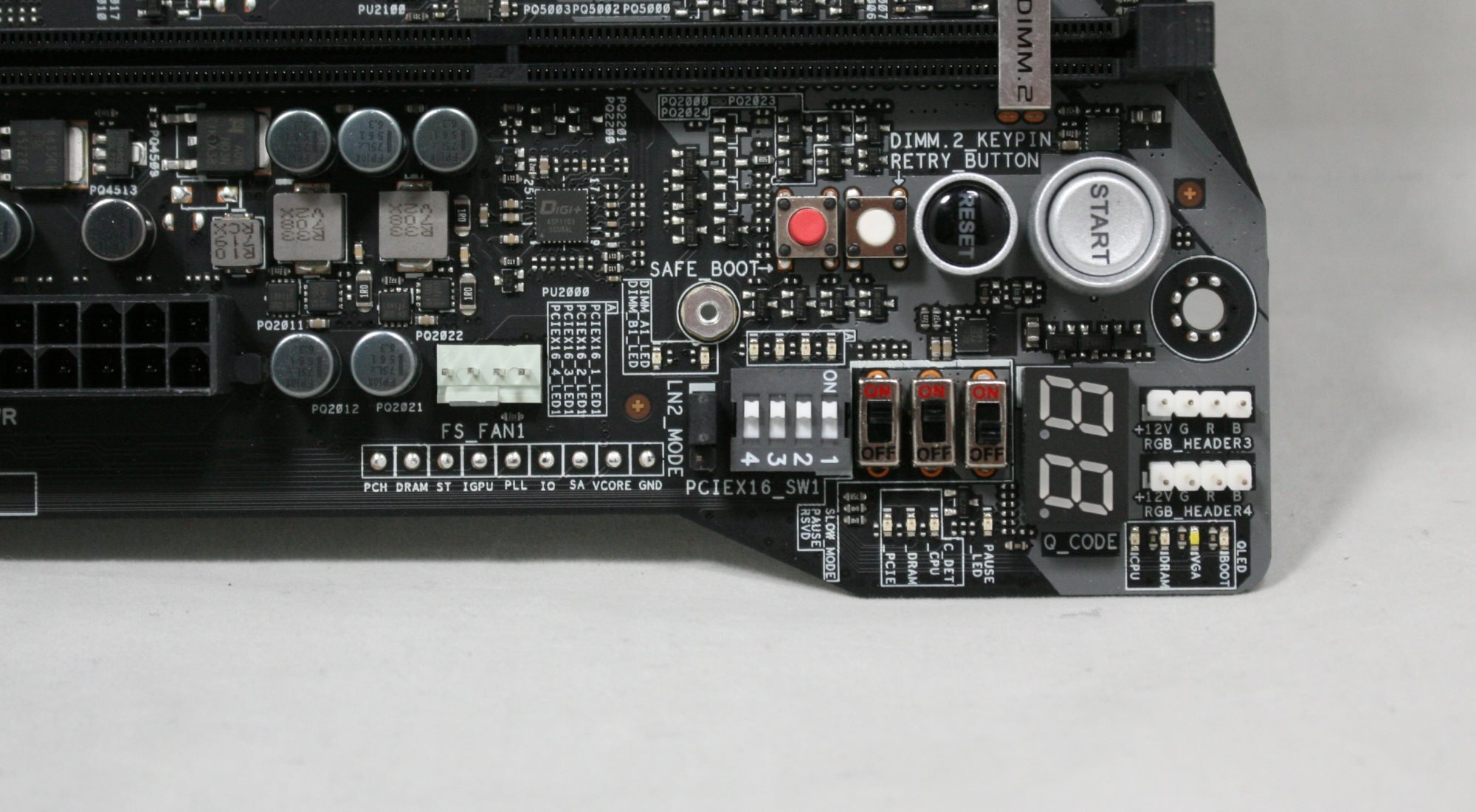
In this upper right-hand corner of the motherboard, pictured above, are a bunch of switches, buttons, and LEDs designed to accomplish a number of things. From the top, we see the circle shaped Start and Reset buttons which sit to the right of more simple retry button (will force a reboot with same settings) and a safe boot function (temporarily applies safe settings to the BIOS in order to boot while still keeping OC settings so they can be adjusted). Below that, on the left, we see a strip of solder circles in order to read voltage directly off the board - a feature great for overclockers. These include VCore, System Agent VCCIO, PLL, iGPU, DRAM, PCH, and Ground read points. To the right of those are an LN2 mode switch used in extreme overclocking to get around cold boot issues, as well as a set of four switches to enable or disable the PCIe slots. The switches to the right are for pause, slow mode, and another reserved for ASUS technicians.
Outside of all that, we can see two (of four total) RGB headers, the Q Code display, and Q LEDs covering Boot (green), VGA (white), DRAM (yellow), and CPU (red). These will stay lit during the boot process if an error is found. Last is a feature for the sub-ambient overclockers in the condensation detection LEDs. These three LEDs will light up when water condensation is detected on three key components - the CPU, DRAM, and PCIe slot. While most will never need this feature, it is a great value-add for the extreme crowd where ice formation, and subsequently melting ice on the motherboard, is quite common.
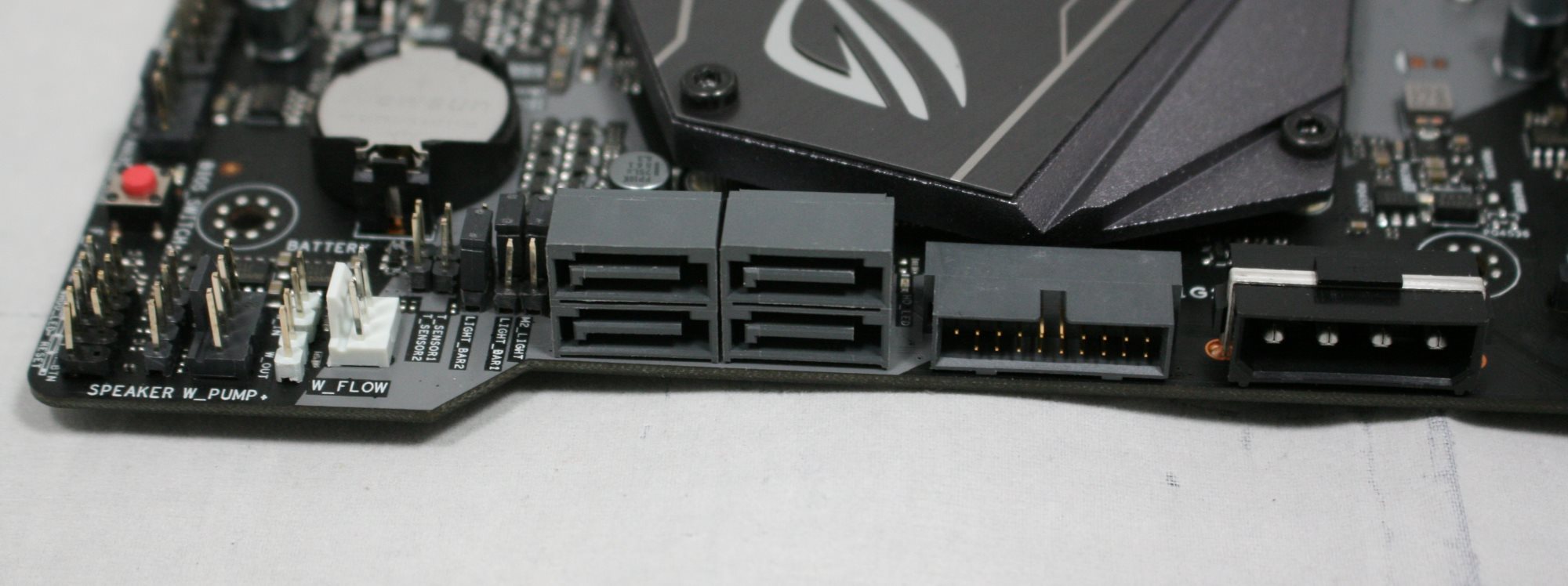
Zooming in on the SATA area above, we are able to see a total of four SATA ports which is two less than the platform offers from the chipset. Presumably, this is to due to space, and that overclockers rarely use more than one drive anyway.

The bottom half of the board consists of the audio portion on the left which has board separation but does not use EMI shielding on the modified Realtek ALC1220. Scattered around the chip are Nichicon Gold series capacitors.
There is a total of six PCIe slots with four full-length and the top three grey ones (also reinforced) pegged for video card duty. You'll notice there are no M.2 slots between the PCIe slots on the board. Both M.2 slots, powered through the chipset, reside on the DIMM.2 add-in-card.

Across the bottom of the board are several other headers and buttons. From left to right we see:
- Front Panel Audio
- FS Fan 2/3 headers
- 2 x RGB headers
- MemOK! button
- TPM header
- 2 x USB 2.0 headers
- Sys Fan header
- Bios Switch
- Front Panel connections
Below is a simplified list of how the PCIe slots will work with each family of CPUs (talking PCIe lanes) when multiple cards are used (the "@" symbol is used to show slot preference for the configuration). PCIe slot numbers are referred to by top-down. In other words, PCIe 1 is the first slot, PCIe 2 below it, and so on.
| ASUS ROG Maximus X Apex CPU PCIe Layout |
||||
| 16-Lane Single |
16-Lane Dual |
16-Lane Tri |
16-Lane Quad |
|
| PCIe 1 | @x16 | @x8 | @x8 | @x8 |
| PCIe 2 | - | - | @x4 | @x4 |
| PCIe 3 | - | @x8 | @x4 | @x4 |
| PCIe 4 (chipset) | x4 | x4 | x4 | @x4 |
| SLI | - | Yes | - | - |
| Crossfire | - | Yes | Yes | If you must |
The back panel IO has a typical assortment of ports, buttons, and plugs with video outputs.
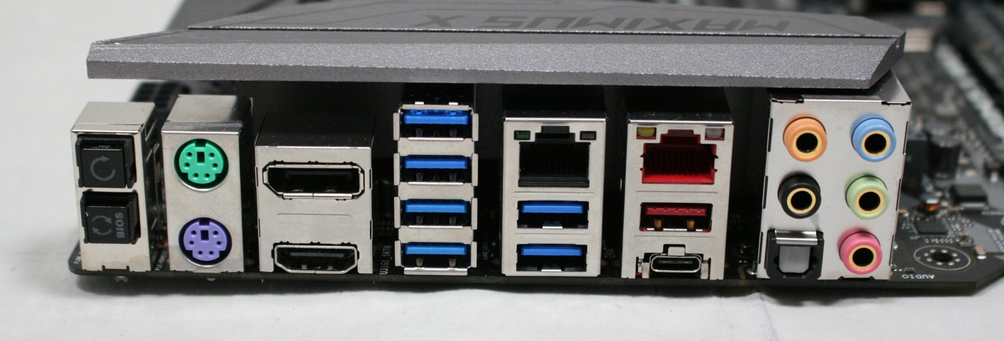
- Clear CMOS and BIOS Flashback buttons
- PS/2 Mouse (green) and Keyboard (purple) ports
- HDMI / DisplayPort (1.2)
- 1 x Wi-Fi
- 1 x Intel GbE
- 1 x Aquantia 5 GbE
- 2 x USB 3.1 (10 Gbps) ports Type-A and Type-C
- 7.1-Channel Audio jacks
In the Box
The accessory stack included with the Apex is comprehensive and has everything users need to get going. It does include a ton of stickers as well as a coaster among the necessities. The DIMM.2 add-in card and brackets are included, as well as extra facias for the removable customization above the first PCIe slot. This package deal has to be applicable to both gamers and overclockers, hence the stickers, the drinks coaster, and other bits.
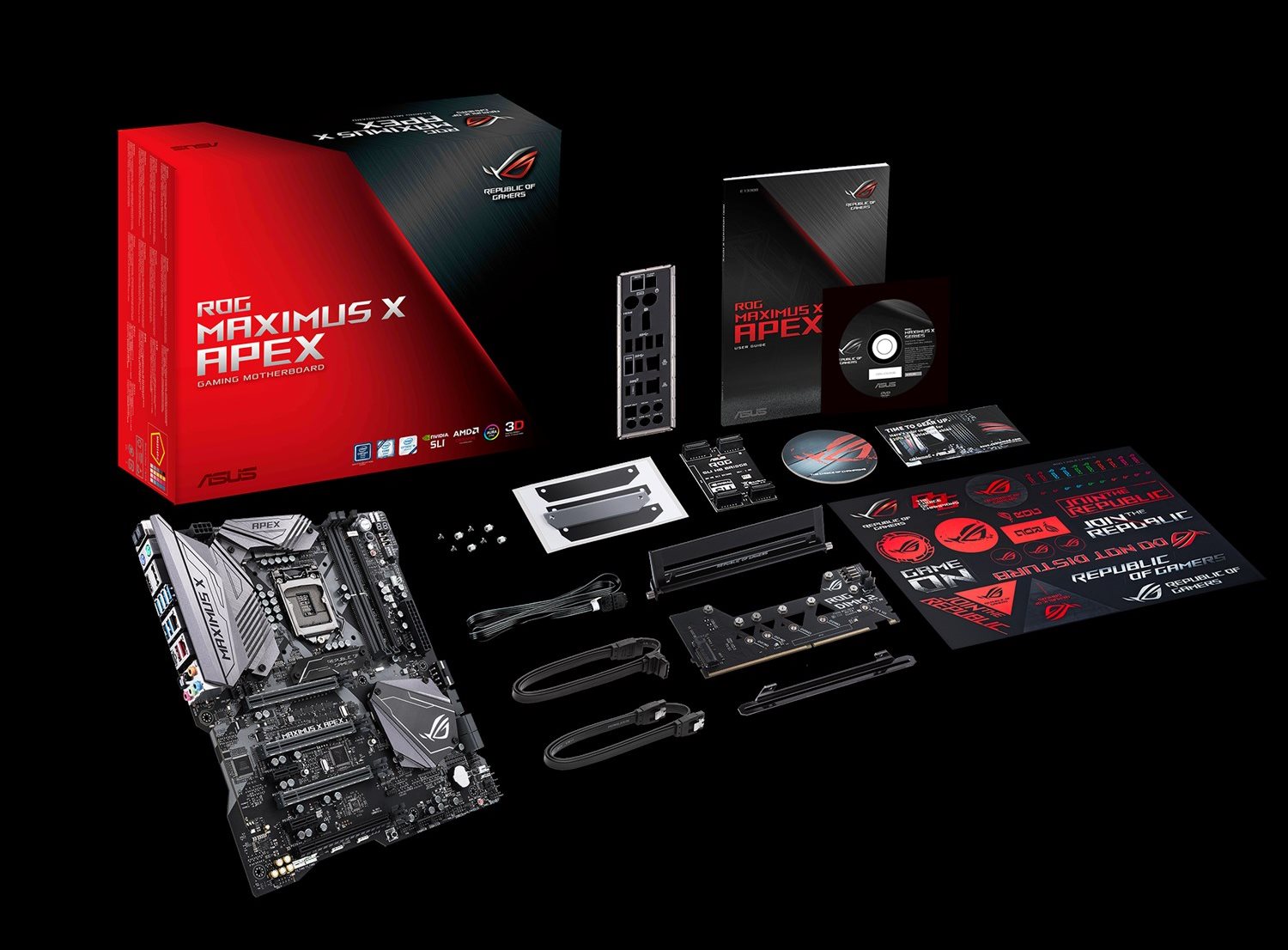
- Motherboard
- I/O Shield
- User's Manual / Driver CD
- 4 x SATA Cables
- ROG DIMM.2 AIC + Fan Stand Pack
- SLI HB Bridge (2-Way -L)
- ROG big sticker
- M.2 screw kit
- Q-connector
- Extension Cable for RGB strips (80cm)
- ROG coaster
- Customizable Name Plate accessory pack
- ROG OC fan bracket pack


39 Comments
View All Comments
evernessince - Friday, May 18, 2018 - link
Correct although technically PS/2 could have lower latency in some situations. PS/2 keyboards and mice work based on interrupts while USB works by polling. In otherwards, when you press a key/click your mouse on a PS/2 device your request is immediately processed. USB on the otherhand waits until the device is next polled.TBH I've never seen a PS/2 vs USB latency test and I've personally never noticed a difference. Then again I haven't tested them strictly against each other on a high refresh rate monitor either.
voicequal - Friday, May 11, 2018 - link
Those active PS/2 to USB adapters never worked very well. Lots of missed inputs or stuck keys. The passive adapters require that the peripheral device switch into a PS/2 mode, supported by some mice, but not all PS/2 in general. Also some KVMs work only with PS/2 if that is your thing.HStewart - Friday, May 11, 2018 - link
10 USB Ports in way more than I can remember on motherboards. My Supermicro Xeon didn't have that many ports on it.But one thing I see missing in motherboards today is Thunderbolt 3 - maybe it is notebook thing - and future generation will have it. What is really nice is you can hook up dual Display Ports on it - not sure how that works with graphics cards today.
DanNeely - Saturday, May 12, 2018 - link
I think I've seen 1 or 2 boards with 12 out the back. 8/10 is around the normal upper limit though, partly for space reasons and partly due to chipset limits. For the last decade or so Intel's offered 14 USB ports on its high end southbridges with a gradually increasing number of the total supporting USB3; since most mobos have 2 or 3 on board headers for front panel ports or various misc internal uses (eg a few PSUs that connect to an internal 2.0 header to report stats) that leaves 8 or 10 total ports free for the back panel. Mobo vendors can get around this a bit by using onboard hubs or controllers (until recently this was the only way to get 10Gb ports), but to a large extent that's faking it until they can't make it. With a hub because you end up needing to know exactly what's going on inside the board if you need to connect multiple high speed devices at once to keep them from bottlenecking each other. PCIe controllers either end up with the same bottleneck problem, or if they have enough lanes to avoid it end up eating the equivalent number of SB ports instead.I've seen a few rumors that Intel's planning to integrate TB3 directly into the platform without needing a separate controller in the future. OTOH unless they add extra PCIe lanes to the CPU it's still probably going to be rare on desktop boards. TB3 is PCIe3 x4 equivalent, so a single connection on the southbridge could eat all of its bandwidth to the CPU. On most laptops to avoid that (and presumably to simplify the GPU out signalling) they use lanes from the CPU instead. On enthusiast desktops those 16 lanes are normally all used for the GPU though, and since PLXes PCIe switches are stupidly expensive now ($80 for a x16 to two x16 model) the only way to do that would be to limit the GPU to x8 instead of x16. In the real world that wouldn't matter much; but marketing is aimed at the clueless and a lot of them would freak.
Destoya - Wednesday, May 16, 2018 - link
The Asus Crosshair VI Hero has the most USB ports of any boards I'm aware of. 2x USB 3.1, 8x USB 3.0, and 4x USB 2.0 on the back panel for a total of 14, though to be fair it only has a single LAN port and no display out. Somewhat ironically for the new Crosshair VII, they dropped two of the USB 2.0 ports for a PS/2 combo port.DanNeely - Wednesday, May 16, 2018 - link
AMD's got a slightly higher max USB port count than Intel, 2 3.1g2 ports, 10 3.1g1 (4CPU, 6 chipset), and 6 2.0 ports; but even there that board is using at least one 3rd party controller for the front panel 3.1g2 header (or they could be routing the chipset ports to that header and using the 3rd party controller on the back).swapping 2 of the 2.0 ports for a PS/2 seems reasonable to me; some people want them (ie those whose high end keyboard is more than a few years old and doesn't support N-key rollover via an extension to the original ~20 year old spec/driver); and the list of devices that have interference problems one 3.0 ports is very short so not many people need more than 1 or 2).
OTOH other than cost reasons or wanting to keep space for their logo I don't see any reason they couldn't've added both; there seems to be enough back panel space for another stack of ports.
StevoLincolnite - Friday, May 11, 2018 - link
You could add another 5+ USB ports on the back I reckon.I can't be the only one with half a dozen external HDD's?
sibuna - Saturday, June 2, 2018 - link
if you are seriously using 1/2 a dozen external USB HDDs just build a NAS, it will serve you betterdgingeri - Saturday, May 12, 2018 - link
1. the PS2 ports run off a PS2 to USB adapter on the board anyway, so they really aren't proper PS2 ports. The X390 chipset doesn't support any path for PS2 ports. So, there really is no advantage on that.2. Those PS2 ports could easily be replaced with 4 USB ports, and they could be run with 2X 2.0 and 2X 3.0. There are enough USB 3.0 ports available from the chipset to do that. USB keyboards run better directly off the root hub anyway. The problems most people have with them having lost input usually comes because the keyboard is being run off a hub. On top of that, I know from direct experience, most USB hubs have major reliability and operational problems. I do my best to avoid running anything through a hub these days because of the repeated and consistent problems I have had with them. I seem to find a good hub once in a while, only to have it die a couple months later. We NEED those ports on the back of those boards, and then some dumb engineer comes up with the idea to use 2 of those ports to make one USB-C header for some front panel port that is supported by only 1 case. My Maximus X Hero Wifi has only 8 ports, so I'm stuck with running my UPS, Nostromo, and mouse off a hub, which is not what I like.
3. There are a LOT of people who go for such advantages in hardware who are just fantasizing over it making them a better player, when it simply won't help. So, stop with the idea that any more than a very bare few actually need PS2 ports.
DanNeely - Sunday, May 13, 2018 - link
This is a Z370 board, and Z370 still has an LPC bus (a quasi-serial version of the ancient ISA bus) which has been the traditional location to mount the control chip for PS2 and other ultra-legacy IO ports. Without scouring the board images itself to figure out what controller is being used, I can't answer how it's being connected but the chipset does have the IO needed to support a non-USB PS2 port.And while the chipset does have theoretical additional USB3 lanes available, it doesn't have free HSIO ports to run them on without going into configuration hell where using feature X disables feature Y, Z370 has a total of 30 of them to split among USB3, SATA, and PCIe lanes from the chipset. The board breaks down as:
1 Intel network
1-4 AQC108 5GBe (maybe only 1-2, the Aquitania page doesn't differentiate between requirements for their 5 and 10Gb controllers)
1 Realtek audio
4+1+1=6 PCIe lanes
4 Sata
4+4=8 M.2 slots
6+2 USB3.0 (back panel and front panel header)
2 ASM USB3.1g2 controller
That adds up to 31-34 already so at least one item is already being switched on/off depending on what else is in use.
https://content.hwigroup.net/images/editorial/1920...